Process Steps
Function
Process steps are used to construct processes.
- "A Process is depicted as a graph of Flow Elements, which are a set of Activities, Events, Gateways, and Sequence Flows that define finite execution semantics."
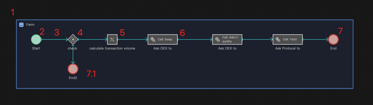
A Web3 farmer performing liquidity mining may execute the following actions in sequence:
Start -> Check funds and market prices -> Calculate transaction volume -> Purchase paired tokens -> Add DEX liquidity -> Stake LP tokens on the protocol -> Complete
The mining process can be modeled as below:
- Process
- Start Event
- Sequence Connector
- Gateway
- Compute
- Ask
- End Event
Categories
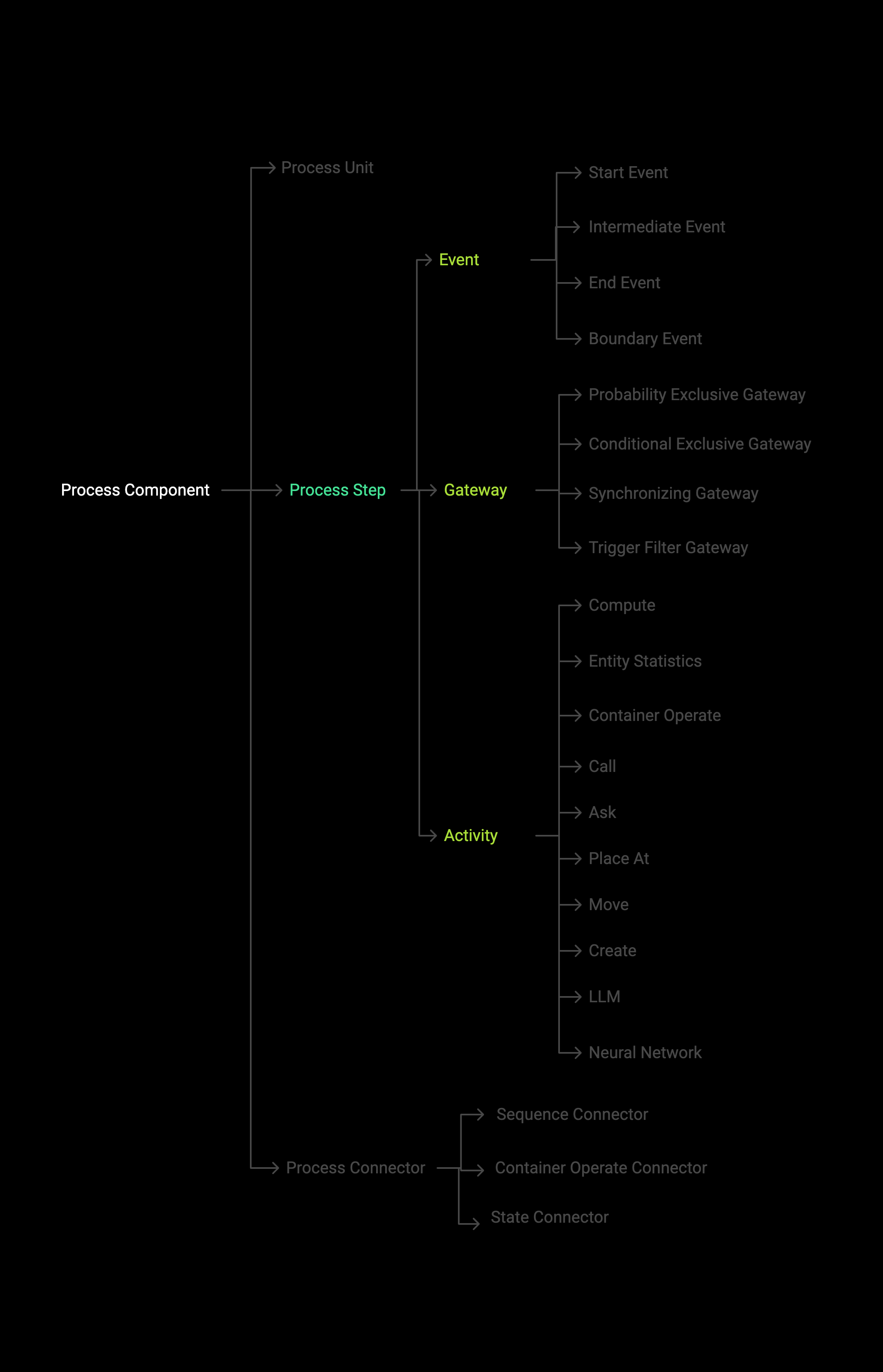
Key Responsibilities of Element Categories
- Events manage the creation, transmission, and destruction of process Triggers.
- Gateways control the selection of Trigger flow paths.
- Activity components implement the logical effect of a single action.
- Process Connectors connect components to express execution order (Sequence Connectors), container operation (Container Operate Connectors), and data passing(State Connectors).
Process Syntax (Placement Rules)
- All process steps can only be placed within process objects.
- A process can only begin with a Start Event and end with an End Event.
- A process has only one start event and at least one end event.
- There are no syntax restrictions on the sequence of other components between the start and end events within the process, provided they are connected logically.
Process Execution Mechanisms
Process Execution Flow
The execution of a process is initiated by a Trigger. The mechanism works as follows:
- A Trigger is created and activated by the start event (either actively or passively), and it proceeds along the Sequence Connector.
- When the Trigger arrives at any process step component, it initiates its operation. After the operation is completed, the Trigger continues to flow along the Sequence Connector.
- The execution of the entire process ends when the Trigger reaches any end event, at which point it is destroyed.
The simulation may not destroy all Triggers at the end; some Triggers may still remain in the process after the simulation is completed. Information can be viewed under the Output Tab in the Console. However, this does not necessarily indicate a bug in the model.
Process Parallel Forks
Multiple sequence branches and inclusive gateways will produce process parallel forks.
-
Multiple sequence branches
When a non-exclusive Gateway component in the process is connected to components with multiple Sequence Connectors, multiple sequence parallel forks are produced.
-
Fork starting
When a parallel fork occurs, the process Trigger will be "split" into multiple "sub-Triggers" and flow along each Sequence Connector simultaneously, thus triggering the components connected by these Sequence Connectors to run at the same time.
-
Fork ending
Use the Synchronizing gateway to "merge" after the fork, each forked sub-Trigger is destroyed, and the original Trigger continues to flow along the Sequence Connector.
- If the synchronizing gateway is not used correctly for merging the forks, it could lead to the model running incorrectly.
- When a mutually exclusive gateway has multiple subsequent branches, any Trigger will only follow one of these branches. Even though it might seem like the process is forking, it isn't, and therefore there's no need to use a synchronizing gateway. For more details, refer to the Gateways chapter.
Suppose there is a variable Count initialized to 0. An increment operation (+1) is performed on Count in 2 parallel forks of the process and then ends after merging.
- Process steps can be used not only to build process objects (instances), but also to construct process blocks (definitions). The operation methods are completely the same.
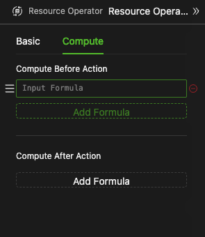
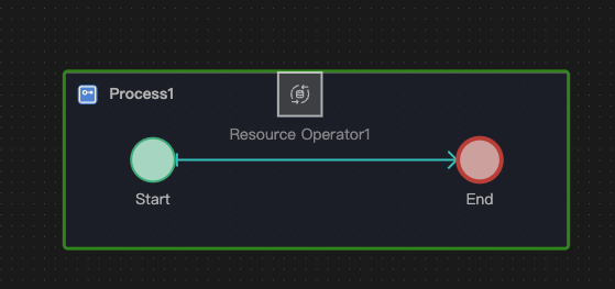
Compute Before or After Action
-
All process steps can be considered as an execution step. Computation can, in principle, be performed before and after this step. For special cases such as Start Event, End Event, Gateway, and other process steps, please refer to the relevant chapters for their computation mechanisms.
ExampleNecessary computation before and after the transaction,
- Compute before action: You can compute the transaction volume and transaction fee before a commodity exchange(resource operation) action.
- Compute after action: Update the latest price after the exchange is successful.
-
The formula input method is the same for all input boxes in HoloBit. For more details, please refer to the Compute component.
Data Output of Activity Elements
-
Some activity components will output action result data, such as Ask components will output the found target entity, Move components will output the distance and angle change of this move, etc., see the corresponding components.
-
The output data can be used in this component action after the computation using the
This.output_key_nameform, or in any formula after the process using thecomponent_name.output_key_nameto access.
Evidently, the data output of a process action object can only be accessed after the action has been performed, as there is no output before the action occurs. Consequently, the preceding components cannot obtain the output results.
-
The output of all components cannot be modified.
-
Register Mechanism
The output data of process action components is bound to a Trigger. When multiple Triggers flow within a single process, the system employs a register mechanism to ensure that subsequent components can correctly access the output data from preceding actions. This mechanism is identical to the register mechanism for process temporary variables.
-
For Process Interfaces and Data Passing, please see the relevant chapter.
Process Modeling
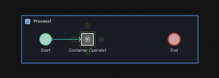
Placing Components into the Process
- When the process is in the expanded state, process components or data components can be directly dragged and dropped into the process canvas. In this case, the process's outline will highlight, indicating valid modeling.
- Alternatively, if you have entered the dedicated canvas of a Process (e.g., by double-clicking it), you can drag process components directly onto this canvas.
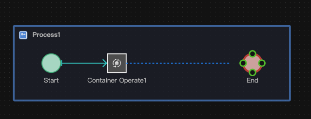
Connecting to an Existing Component
-
Hover your mouse over the source component from which you want to draw a connection. "Plus" (+) connection points will appear around its border.
-
Left-click (and hold) on one of these "+" connection points. Anchor points on other legally connectable target components will light up. Drag your mouse to an anchor point on the desired target component and release the mouse button. A Process Connector (typically a Sequence Connector by default) will be created.
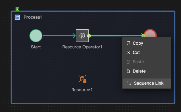
Changing Connector Type
If the Connector type is not what you intended after the connection is complete, you can change the type of the Connector via the right-click menu.
Currently, HoloBit intelligently determines the unique, correct type of Process Connector (Sequence, State, or Container Operate) that can exist between any two specific types of process components. Therefore, manual changing of Connector types is generally not required. The system creates the appropriate Connector automatically.
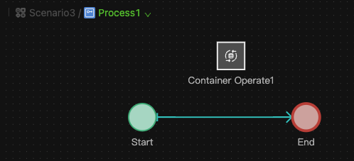
Adding a Next Component Directly from an Existing One
-
Hover your mouse over an existing component. "+" connection points will appear.
-
Single-click one of the "+" points. A selection palette (component chooser) will pop up, showing valid next components.
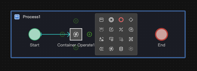
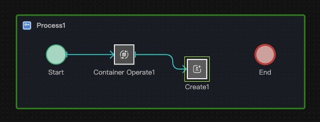
-
Click the desired component from the palette. The system will automatically place it on the canvas and connect it to the source component with the appropriate Process Connector. Click again on the canvas to finalize its position.
Inserting a Component between Two Connected Components
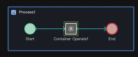
- Hover your mouse over an existing Process Connector connecting two components. An "Add Component" button (often a "+") will appear on the Connector.
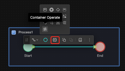
- Clicking this button opens the component selection palette.
- Choose the component you want to insert. It will be placed on the Connector, automatically breaking the old Connector and forming new Connectors to and from the inserted component.
The component selection palette that appears (when generating the next component or inserting one) is context-aware. It only lists process components that are syntactically valid to connect from the current source component, according to HoloBit's process modeling rules.